Greentech International (Zhangqiu) Co., Ltd.
Greentech Industry (Jinan) Co., Ltd.

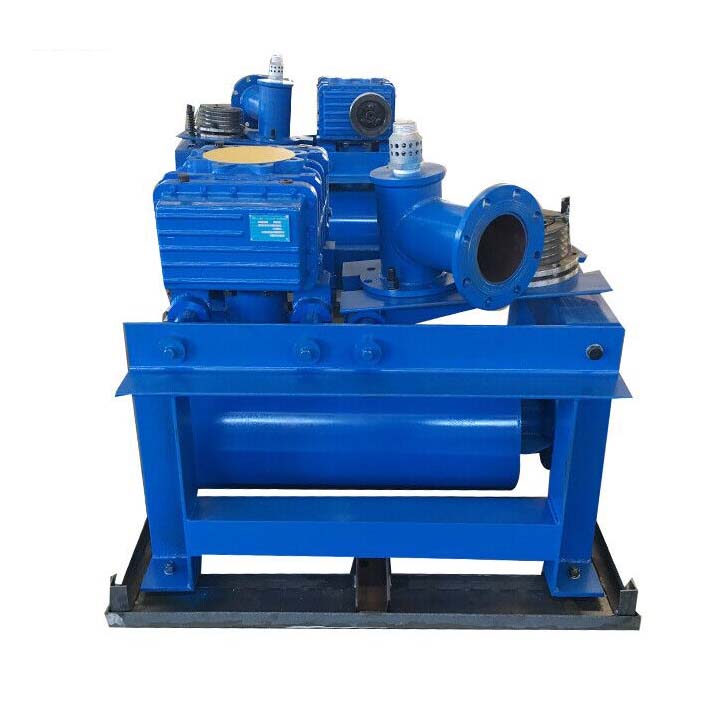
Rotary lobe machines are used in all those applications where higher flow rates are required than those of side channel machines (up to 20000 m3/h), with discharge pressure up to 1 bar rel. or suction vacuum up to -500 mbar rel.
The volumetric efficiency of a lobe machine is constant, thus allowing it to operate with a roughly constant flow rate while varying the pressure differential. Since there is no friction between the lobes and between the lobes and the stator, and therefore there is no wear of these components, the volumetric efficiency is invariable over time.
Furthermore, since there is no friction between the lobes and between the lobes and the stator, no lubrication in the compression chamber is necessary. The conveyed gas is therefore totally oil-free.
Typical delivery compositions
Rotary lobe machines are normally supplied as a "Compact Group", in which the support base of the machine body is integrated with the delivery silencer while the suction silencer is integrated into the filter.
The transmission between machine and motor is carried out by belts and pulleys or by gear reducer for the highest powers.
The Units are completed with overpressure valve or vacuum breaker, check valve, anti-vibration supports, elastic connection sleeve and possibly soundproofing cabin with extraction fan, pressure gauges and vacuum gauges, vacuum start valve and other accessories on request.
The GREENTECH Sales Service, in synergy with its Technical Service, is able to study and propose, on the basis of customer requests, the "Complete Package Groups" that best meet the specific needs and peculiarities of the plant.
cast iron casing (stator and bottoms), steel rotor, vanes in non-sparking stratified plastic laminate;
sealing between stator, bottoms and covers making up the machine body by means of flat gaskets and/or toric rings;
mechanical seal on the shaft which, depending on the operating pressure, can be single or double oil thru-bar;
coupling joint between compressor and electric motor which, in the event of breakage of the elastic buffers, does not allow the drive and duct parts to come into contact; transmission protection casing in non-sparking material;
electric motors in explosion-proof execution, protection mode "d", with specific marking Ex II 2 G, minimum complementary marking Ex-d IIB T3.
In the event that the surrounding environment is classified as Zone 2, for which Category 3 equipment is therefore allowed for Group II, the electric motor of the compressor may be in non-sparking execution, protection mode "n", with specific marking Ex II 3 G, complementary marking Ex-nA II T3.
The actual compressor body can be proposed with cooling by ambient air which, sucked in by an axial fan mounted on the coupling to the motor, is conveyed between the finned external surface of the stator and a conveyor casing enveloping the compressor body itself. Or, with cooling by water circulation in the jacket wrapping around the body.
Heat transfers from metal to water more effectively than from metal to air. The temperature reduction of the compressed gas is therefore greater in water-cooled compressors. They can therefore compress the gas at higher pressures and cover a range of suction flow rates significantly higher than that of air-cooled compressors.
Copyright © 2020 Greentech International (Zhangqiu) Co., Ltd. | All Rights Reserved 鲁ICP备12007127号 Technical support:Xintuweb